Cleanroom Challenges in the Pharmaceutical Industry

Kjeld Lund October 30, 2024
Pharmaceutical Manufacturing of Drugs

Introduction


Cleanrooms are a crucial aspect of the pharmaceutical industry, where high standards of cleanliness, environmental control, and contamination prevention are paramount. These controlled environments enable the production of drugs, biologics, and other therapeutic products under conditions that minimize contamination from particles, microorganisms, and chemicals. Despite stringent regulations and advanced technologies, cleanroom operations in pharmaceuticals face a number of challenges, particularly as new products like cell and gene therapies demand higher standards of sterility and precision. This article delves into some of the primary challenges in maintaining cleanrooms within the pharmaceutical sector, examining both traditional difficulties and emerging complexities.


1. Stringent Regulatory Compliance


Pharmaceutical cleanrooms must comply with a wide range of regulations, including those set by the Food and Drug Administration (FDA), European Medicines Agency (EMA), and international guidelines like ISO 14644, which defines cleanroom classifications based on particle counts. These standards require not only stringent environmental controls but also regular validation, testing, and reporting.


  • Challenge: The evolving regulatory landscape can be difficult to keep up with, especially with the increasing scrutiny on sterile processing and aseptic manufacturing. New guidelines often require changes in equipment, testing protocols, or operational procedures, adding complexity to already rigid processes.
  • Solution: Pharmaceutical companies need robust compliance teams and flexible systems that can adapt quickly to regulatory updates, including automated reporting and digital compliance monitoring tools.


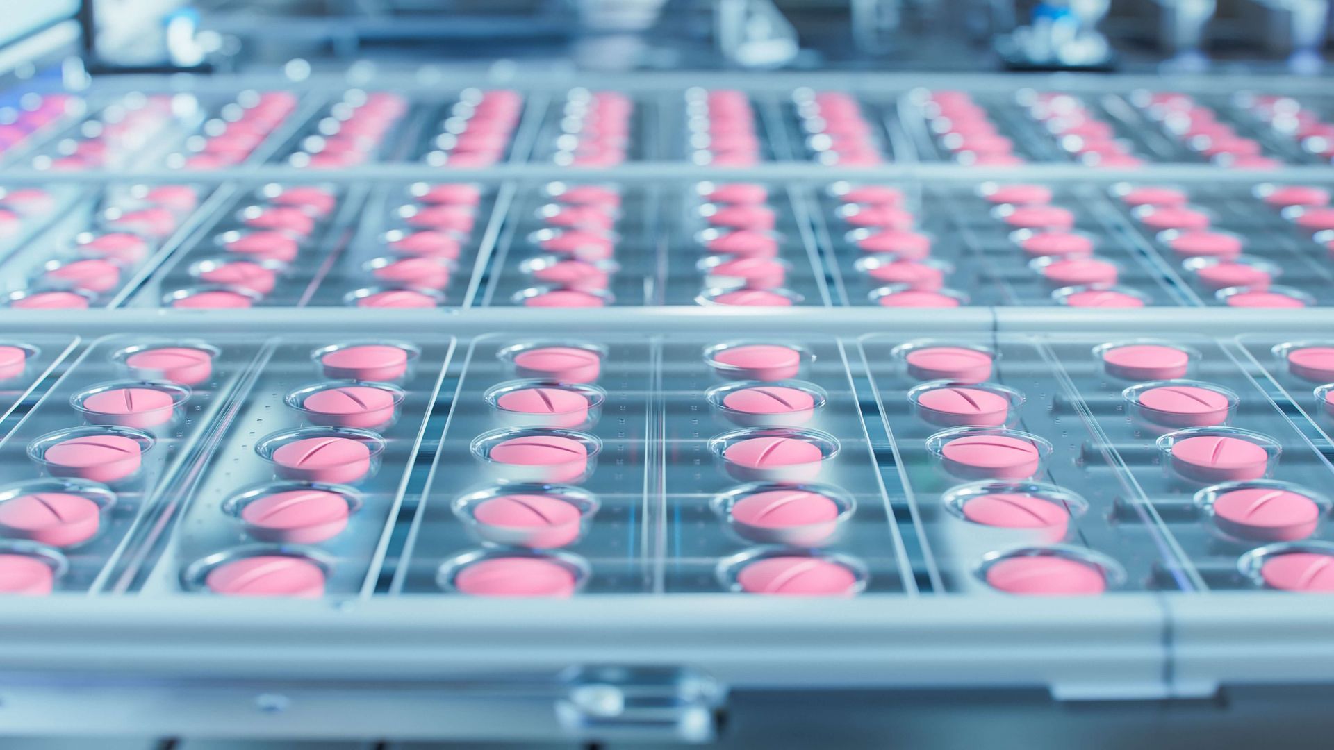
2. Particle and Microbial Contamination Control


Particulate and microbial contamination in cleanrooms can lead to product recalls, batch losses, and potentially harmful impacts on patient health. Cleanrooms are designed to control particles from various sources, including humans, materials, equipment, and ventilation systems. However, achieving and maintaining this level of control can be an ongoing challenge.


  • Challenge: Even with stringent gowning procedures and air handling systems, particles can be introduced by personnel, equipment wear, and even the production materials themselves. Microbial contamination is particularly challenging as many microbes can survive in low-nutrient environments and persist in hard-to-clean areas.
  • Solution: Enhanced monitoring with real-time particle and microbial detectors, improved cleaning protocols, and implementing advanced filtration systems, like HEPA and ULPA filters, can reduce the risk of contamination. Routine personnel training on contamination control procedures is also crucial.


3. Environmental Monitoring and Data Management


Continuous environmental monitoring is required to maintain cleanroom standards and detect potential contamination issues before they impact product quality. Data collected on temperature, humidity, airflow, pressure differentials, and contamination levels must be managed meticulously.


  • Challenge: Managing vast amounts of data from multiple sources can be difficult, especially if facilities lack centralized, automated systems. Manual data management increases the risk of errors, potentially leading to compliance violations.
  • Solution: Automated environmental monitoring systems that integrate data collection, storage, and analysis in real-time are increasingly used in pharmaceutical cleanrooms. Cloud-based data storage can also improve accessibility and traceability while reducing the potential for human error.


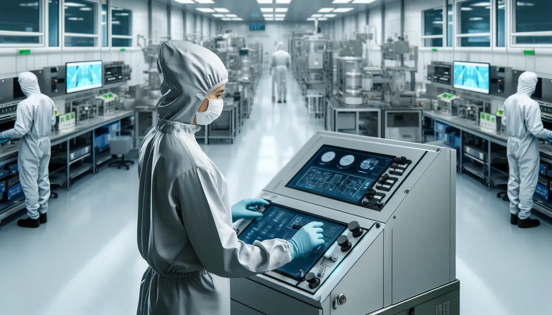
4. Personnel-Related Contamination Risks


Personnel are often the largest source of contamination in cleanrooms, despite rigorous gowning and hygiene protocols. Human skin, hair, respiratory droplets, and even movement can introduce particles and microbes into a sterile environment.


  • Challenge: Managing contamination risks related to personnel requires a fine balance between rigorous protocols and practical usability. High turnover rates in the industry can make consistent training and enforcement challenging.
  • Solution: Automated systems like robotics and remote-operated tools can minimize the need for human presence in critical areas. Virtual reality (VR) training for cleanroom protocols also shows promise in improving staff performance and awareness of contamination risks.


5. Energy and Cost Efficiency


Cleanrooms are energy-intensive environments due to the need for high-efficiency ventilation systems, temperature and humidity controls, and rigorous cleanliness standards. Maintaining such environments requires significant energy input and cost, which can be challenging to manage sustainably.


  • Challenge: Balancing operational costs with environmental responsibility is difficult, especially as cleanroom standards continue to become more demanding. Cleanrooms operating at ISO Class 5 or better are particularly costly, requiring 100% HEPA filtration and maintaining positive air pressure.
  • Solution: Energy-efficient technologies, such as advanced HVAC controls, energy recovery ventilators, and variable-speed motors, can help reduce costs. Lean manufacturing principles and optimizing cleanroom design to reduce unnecessary air exchanges can also improve energy efficiency without compromising cleanliness.


6. Cross-Contamination in Multiproduct Facilities


Many pharmaceutical companies operate multiproduct facilities where different drugs or biologics are manufactured in shared spaces, raising the risk of cross-contamination. This issue is particularly pressing for facilities producing both traditional drugs and new biologics or cell and gene therapies, which require different contamination control standards.7


  • Challenge: Ensuring no cross-contamination between products requires robust cleaning protocols, validated containment procedures, and sometimes complete room shutdowns for cleaning. Multiproduct facilities may also need to segment their cleanrooms or install specialized air handling to prevent cross-contamination.
  • Solution: Modular cleanroom setups allow sections of a cleanroom to be isolated and dedicated to a specific product for a particular production run, reducing the risk of cross-contamination. Dedicated air-handling systems for each production area also enhance containment.


7. Risk of Contamination in New Therapeutic Product Manufacturing


Innovative therapies such as cell and gene therapies pose unique challenges for cleanroom environments due to their sensitivity to environmental factors and the need for even higher sterility levels. These therapies are often produced in small batches, increasing the risk of contamination from any procedural lapse.


  • Challenge: Cell and gene therapies often require handling of live cells and genetic materials, which are susceptible to contamination that could ruin the entire batch and impact patient safety. These therapies also require a higher level of operator interaction, increasing contamination risks.
  • Solution: Single-use technologies (SUTs), such as disposable bioreactors, tubing, and filters, reduce the risk of contamination by eliminating the need to sterilize reusable components. Closed-system processing, where production occurs in a sealed environment, is another solution gaining traction in cell and gene therapy manufacturing.


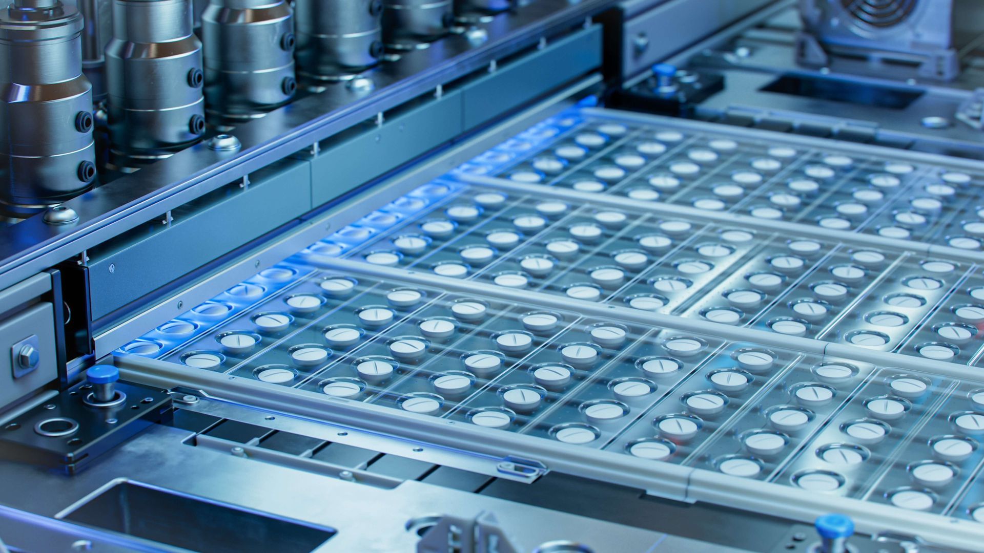
8. Cleanroom Automation and Technological Integration


The complexity of modern cleanroom operations calls for sophisticated automation, such as robotic systems, process automation, and remote monitoring. Automation is highly beneficial in reducing human error and contamination, but it also introduces new challenges.


  • Challenge: Integrating automation into cleanroom environments is often challenging due to compatibility issues with existing systems and the potential for introducing particles through mechanical wear. Additionally, the high upfront cost of automation technology and the need for specialized staff training can be prohibitive.
  • Solution: Robust maintenance programs for automated equipment and careful planning of automation integration can mitigate these risks. Implementing modular automation that can be scaled or adjusted as needs evolve is another effective strategy.


9. Quality Control and Sterility Testing


Quality control in cleanrooms involves regular sterility testing and validation procedures to ensure compliance and maintain product safety. The sterility testing process is often time-consuming and costly, particularly for high-value batches like biologics or gene therapies.


  • Challenge: The challenge lies in balancing the thoroughness of quality control with production efficiency. Traditional sterility testing methods can be time-consuming, with long incubation periods that delay production timelines.
  • Solution: Rapid microbial detection methods, such as ATP (adenosine triphosphate) bioluminescence, can help reduce the time needed for sterility testing. In addition, advanced methods like real-time PCR (Polymerase Chain Reaction) enable faster microbial detection, facilitating quicker batch release.


Conclusion


Cleanroom challenges in the pharmaceutical industry are multifaceted, spanning from stringent regulatory compliance to managing personnel-related contamination risks. With the rise of advanced therapeutic products like cell and gene therapies, the demand for precise control and contamination prevention has never been higher. While technological advances in automation, monitoring, and containment offer potential solutions, the industry must continuously adapt to maintain the high standards required for patient safety and product efficacy.


Automated pharmaceutical production line filling vials with clear liquid.
By Kjeld Lund 27 February 2026 February 27, 2026
Cleanroom Commissioning: Integrating Building Services and Process Requirements 1. Introduction Cleanroom commissioning is a structured, engineering-driven process that ensures building services, HVAC systems, automation controls, and process-specific requirements are harmonized before qualification and routine operation. While ISO 14644 defines the performance criteria and GMP Annex 1 establishes regulatory expectations, commissioning verifies that the facility’s mechanical, electrical, and control systems have been functionally tested, documented, and optimized to support cleanroom performance. Effective commissioning reduces qualification risk, compresses project timelines, and provides a reliable foundation for DQ–IQ–OQ–PQ activities. This article outlines a technically rigorous approach to commissioning cleanrooms by integrating building services with process and operational needs. 2. Commissioning Objectives and Scope Cleanroom commissioning goes beyond standard HVAC commissioning by incorporating contamination-control, process compatibility, and regulatory compliance considerations. Primary objectives include: Confirming that building services deliver the environmental conditions required by the URS. Verifying that HVAC, electrical, monitoring, and automation systems perform according to design intent. Ensuring seamless integration of process equipment, personnel flow, and material flow. Establishing documented evidence that supports subsequent IQ/OQ/PQ activities. Commissioning scope typically covers mechanical (HVAC), electrical, process utilities, automation, controls, fire protection, and architectural systems relevant to environmental stability. 3. Relationship Between Commissioning and Qualification Commissioning and qualification are distinct but interdependent processes. Commissioning verifies functional performance and ensures systems operate safely, reliably, and in accordance with the design. Qualification demonstrates that the facility meets regulatory, contamination-control, and process requirements defined in the URS and CCS. A well-executed commissioning effort reduces qualification deviations, accelerates OQ, and provides high-quality baselines for PQ. 4. Commissioning Workflow Structure A structured commissioning plan provides transparency, traceability, and alignment with design requirements. Typical stages include: Pre-Commissioning: Documentation review, installation checks, and power-up inspections. Static Commissioning: Verification of mechanical and electrical installation quality. Dynamic Commissioning: Functional testing under powered and operational conditions. Integrated Systems Testing (IST): Validation of system-to-system interactions, including alarms, interlocks, and fail-safes. Handover to Qualification: Compilation of commissioning results and resolution of deficiencies. Each stage must be traceable to the design documents, URS, and Basis of Design (BOD). 5. HVAC Commissioning Essentials HVAC systems are the backbone of cleanroom environmental control. Commissioning must demonstrate that airflow, pressure, temperature, and humidity targets are reliably achievable. Critical HVAC commissioning activities: Airflow verification: Measuring supply, return, and exhaust volumes to confirm balance and cascade stability. Pressure cascade establishment: Testing differential pressures between zones under at-rest and disturbed conditions. Filter installation integrity: Ensuring HEPA/ULPA filters and housings are correctly seated before OQ integrity testing. Damper and control valve tuning: Aligning actuator positions and control algorithms with design assumptions. Thermal stability verification: Confirming temperature and humidity responsiveness under varying loads. Mechanical commissioning data form the baseline for OQ environmental verification. 6. Integration of Building Automation and Monitoring Systems Cleanrooms rely on automation for stable control of critical environmental parameters. Key commissioning considerations: BMS/EMS functional testing: Verifying setpoint control, signal scaling, trending, and alarm logic. Interlocks and dependencies: Testing door interlocks, pressure-loss alarms, fan failures, and safe-shutdown sequences. Sensor calibration: Ensuring pressure, temperature, humidity, and airflow sensors are calibrated and traceable. Redundancy and failover: Validating that redundant fans, UPS systems, or emergency power supplies respond appropriately. Automation commissioning provides the functional evidence required to support qualification, monitoring strategy development, and ongoing lifecycle control. 7. Integration of Utility and Process Services Process utilities must operate in harmony with the cleanroom environment, especially in GMP-regulated facilities. Core utility commissioning activities include: Clean utilities: Verifying functionality of compressed air, chilled water, process gases, and vacuum systems. Gowning and hygiene facilities: Ensuring airlocks, sinks, and hand dryers support contamination-control workflows. Waste and exhaust systems: Confirming containment and flow direction for hazardous or high-particulate loads. Lighting and emergency systems: Ensuring visual quality and safety without introducing contamination or turbulence. Utility commissioning ensures the cleanroom can support full process operations without compromising environmental conditions. 8. Architectural and Envelope Commissioning The cleanroom envelope establishes the physical barriers needed to control contamination and maintain pressurization. Key architectural commissioning checks: Verification of panel integrity, sealing, and non-shedding finishes. Door alignment, closure force, and leakage performance. Integrity of glazing, pass-throughs, and service panels. Surface continuity, cleanability, and compliance with hygienic design principles. Access to mechanical spaces without exposing clean areas to uncontrolled contamination. Architectural performance strongly influences the ability to maintain pressure cascades and achieve classification targets. 9. Integrated Systems Testing (IST) IST validates the full interaction of cleanroom subsystems under realistic scenarios. This is particularly important for GMP facilities where system interdependencies affect contamination control. Typical IST tests include: Power failure and restoration: Verifying controlled shutdown and recovery of HVAC, monitoring, and interlocks. Fire alarm activation: Confirming damper positioning, pressurization shifts, and emergency responses. Door operation simulations: Evaluating transient pressure responses and interlock performance. Equipment heat-load simulation: Testing environmental stability under modeled process conditions. HVAC-facility coordination: Ensuring airflow patterns remain stable when multiple units ramp up or modulate. IST results are essential inputs for OQ/PQ risk assessment. 10. Documentation and Traceability Commissioning documentation must be complete, organized, and traceable to support qualification and regulatory audits. Required documentation typically includes: Commissioning plans, protocols, and test scripts. Installation and functional verification records. Calibration certificates and equipment lists. As-built drawings, control sequences, and airflow balance reports. Deficiency logs and corrective actions. Final commissioning summary report. A thorough documentation package reduces ambiguity during qualification and provides clear evidence of engineering due diligence. 11. Transition to Qualification (IQ–OQ–PQ) After commissioning, qualification teams rely on the commissioning data as verified baselines. Linkages include: IQ: Uses installation records, calibration data, and as-built documentation. OQ: Builds on airflow, pressure, and control-system performance data to verify environmental conditions. PQ: Relies on operational insights from IST and utility tests to validate process performance. A seamless transition between commissioning and qualification minimizes rework and enhances regulatory compliance. 12. Conclusion Cleanroom commissioning is a critical step in ensuring that building services and process requirements form a cohesive, fully functional system before regulatory qualification. By rigorously testing HVAC, automation, utilities, and architectural components—and by validating their interactions through IST—commissioning provides the technical foundation for reliable cleanroom performance. When executed with precision and clear documentation, commissioning strengthens contamination control, reduces risk, and enhances the long-term operational stability of regulated facilities. Read more here: About Cleanrooms: The ultimate Guide
Brown powder exploding against a white background.
By Kjeld Lund February 20, 2026 February 20, 2026
Precision Control of Pressure Cascades in Multi-Zone Facilities 1. Introduction Pressure cascades are a foundational element of contamination control in multi-zone cleanroom facilities. Whether the target is protecting sterile products, preventing cross-contamination, or ensuring environmental containment, the ability to maintain well-defined differential pressures between adjacent rooms is essential for compliance with ISO 14644 , GMP Annex 1 , and sector-specific regulatory frameworks. Precision pressure control enables directional airflow from cleaner to less clean (or, in containment applications, the reverse), ensuring that contaminants cannot migrate across boundaries. This article presents a technically robust, engineering-focused overview of strategies for designing, implementing, and maintaining stable pressure cascades in complex cleanroom environments. 2. Fundamentals of Pressure Cascade Design A pressure cascade establishes a controlled airflow direction between rooms. Cleanrooms typically maintain positive pressure relative to surrounding areas, whereas containment suites (e.g., cytotoxic or BSL environments) may maintain negative pressure to prevent hazardous material release. Key engineering objectives: Maintain defined pressure differentials, commonly 10–15 Pa between critical cleanroom grades and ≥5 Pa between support zones. Ensure airflow directionality remains stable under expected operational conditions, including personnel movement and door cycling. Integrate pressure control with the overall heating, ventilation, and air conditioning (HVAC) strategy and with the facility’s Contamination Control Strategy (CCS). Pressure cascades must be defined during Design Qualification (DQ) and supported by detailed airflow and balance calculations. 3. Determining Target Pressure Differentials Target values depend on regulatory classification, process risk, and architectural constraints. Common industry values: ISO 5 → ISO 7 transitions: 10–15 Pa positive differential. ISO 7 → ISO 8 transitions: 5–10 Pa. Cleanroom envelope → unclassified areas: 10–30 Pa, depending on infiltration risk. Containment zones (negative pressure): –25 to –50 Pa relative to adjacent safe areas, depending on hazard classification. Selection of pressure levels must consider: Leakage paths (e.g., door margins, pass-throughs, panel joints). HVAC supply/exhaust balance requirements. Structural constraints that affect room airtightness. Safety factors for peak infiltration during operations. 4. Supply, Return, and Exhaust Balance Strategies Achieving stable pressure requires precise control of volumetric airflow. Primary balancing strategies: Supply-dominant control (positive pressure zones): Supply airflow exceeds return/exhaust. Exhaust-dominant control (negative pressure zones): Exhaust exceeds supply to maintain containment. Neutral-buffered rooms: Used between zones where either excessive positive or negative pressure would be undesirable. Engineering calculations must account for: Door leakage rates at closed and partially opened conditions. Equipment penetrations and pass-throughs. Variability in FFU and terminal HEPA performance curves. Seasonal density changes in supply air that affect mass flow. Airflow balance typically forms the basis for both initial HVAC design and control-system tuning during OQ. 5. Control System Architecture for Pressure Regulation Modern pressure cascades rely on a combination of hardware and control strategies to ensure stability under dynamic conditions. Essential system components: Differential pressure sensors: High-accuracy transmitters with calibration traceability, placed between each zone pair. Variable Air Volume (VAV) boxes: Modulate supply or return airflow to maintain the setpoint. Exhaust control valves/dampers: Particularly critical in negative-pressure zones. Airflow monitoring stations: Provide mass-flow verification for high-precision control loops. Building Management System (BMS) or EMS integration: Enables setpoint enforcement, alarms, trending, and interlocks. Control strategies: Cascade control loops: Primary (pressure) loop driving secondary (airflow) loops for improved response. Direct supply modulation: Adjusts supply airflow to maintain pressure. Return modulation: Often used where supply airflow must remain stable for temperature or humidity control. Hybrid strategies: Combining supply and return modulation for high-stability applications such as Grade B aseptic areas. 6. Managing Dynamic Conditions and Transients Door openings, personnel movement, and equipment operation introduce transient disturbances that can destabilize pressure cascades. Engineering techniques to manage transients: Airlock design: Provides staged pressure transitions and minimizes direct room-to-room pressure impacts. Interlocked doors: Prevent simultaneous opening of two doors within airlocks. High-response actuators and VAVs: Reduce pressure drift during sudden disturbances. Buffer airflow: Slight over- or under-supply margin to absorb transient conditions. Door automation: Slow-open/slow-close mechanisms reduce airflow shock loads. Transient simulations—either through CFD or simplified airflow modelling—are valuable during DQ for assessing worst-case scenarios. 7. Architectural Airtightness and Leakage Control Room leakage strongly influences achievable pressure stability and energy efficiency. Best practices: Seal all penetrations, utility lines, electrical conduits, and panel joints with low-VOC, non-shedding sealants. Use gasketed, tight-tolerance cleanroom doors with verified leakage rates. Minimize uncontrolled leakage paths within wall systems, ceiling voids, and raised floors. Validate airtightness through room pressure decay tests where appropriate. Improving airtightness often reduces the airflow required to maintain pressure differentials, lowering lifecycle operating costs. 8. Sensor Placement and Calibration Strategies Accurate pressure control depends heavily on proper placement and maintenance of differential pressure sensors. Placement guidelines: Sensors should measure pressure between rooms directly, not relative to corridor air that may fluctuate. Install measurement ports away from supply diffusers and high-velocity zones to avoid local bias. Maintain consistent elevation when comparing multiple sensors for cascade alignment. Calibration considerations: Perform initial calibration during IQ with traceable standards. Recalibrate at intervals defined by risk assessment—typically 6–12 months. Verify readings during every OQ using calibrated reference instruments. 9. Integration With Environmental Monitoring and Alarms Pressure differentials are classified as critical or major environmental parameters depending on the process. Monitoring systems must provide continuous assurance. Key features for compliant systems: Real-time trending with audit trails. Alarm setpoints with justified action/alert limits (e.g., 10 Pa target with 6 Pa alert and 4 Pa action). Door status logging to correlate excursions with operational events. Interlocks that deactivate operations or signal operators when pressure falls below safe limits. Proper alarm integration is a requirement under GMP Annex 1 to ensure ongoing contamination control. 10. Verification and Qualification of Pressure Cascades Pressure cascade performance must be demonstrated through structured qualification activities. During OQ: Measure differential pressure stability under at-rest conditions. Verify response time to disturbances such as door openings. Confirm that airflow balancing matches design assumptions used in DQ. During PQ: Validate pressure maintenance during real operations including personnel activity and equipment heat loads. Demonstrate that pressure excursions do not compromise ISO classification or contamination control. Collect baseline pressure-trending data for future monitoring comparisons. Qualification outcomes must be linked to URS requirements and documented in the facility’s CCS. 11. Lifecycle Maintenance and Requalification Maintaining an effective pressure cascade requires ongoing attention. Key elements: Annual requalification of pressure measurements. Periodic inspection and recalibration of pressure transmitters. Verification of air balance following any HVAC or architectural change. Routine inspection of door seals, gaskets, and damper positions. Trend analysis to identify drift or instability. A robust change-control process is essential; even small modifications, such as replacing a door or altering exhaust ducting, may require partial requalification. 12. Conclusion Precision control of pressure cascades is central to maintaining contamination-control integrity in multi-zone cleanroom facilities. Through careful design, accurate airflow balancing, reliable control hardware, and rigorous qualification, engineers can ensure that cleanrooms consistently achieve the pressure differentials required by ISO 14644 and GMP Annex 1. A disciplined approach supports operational stability, reduces contamination risk, and strengthens long-term regulatory compliance across the cleanroom lifecycle. Read more here: About Cleanrooms: The ultimate Guide
Pink pills in blister packs on an automated production line.
By Kjeld Lund February 13, 2026 February 13, 2026
Advanced Airflow Modelling: Applying CFD in Cleanroom Design 1. Introduction Computational Fluid Dynamics (CFD) has become an essential tool for engineering cleanrooms that meet stringent performance, contamination-control, and regulatory requirements. While ISO 14644 and GMP Annex 1 provide the performance criteria, CFD enables engineers to predict airflow behavior—velocity fields, turbulence, particle transport, and temperature distribution—before construction or modification of a cleanroom. When properly validated, CFD strengthens design decisions, reduces lifecycle risk, and improves operational reliability. This article provides a technically grounded, engineer-focused guide to using CFD in modern cleanroom design, from modelling strategy to validation and integration with qualification activities. 2. The Role of CFD in Cleanroom Engineering CFD supplements traditional engineering calculations by offering a detailed, three-dimensional understanding of airflow patterns. In cleanrooms where unidirectional flow, pressure cascades, and contamination pathways are critical, CFD offers insights that are not achievable through rule-of-thumb design alone. Primary uses of CFD in cleanroom design include: Predicting airflow velocity profiles and identifying turbulence zones. Visualizing unidirectional flow uniformity over process-critical areas. Simulating particle generation, transport, and deposition. Optimizing placement of HEPA filters, returns, and make-up air inlets. Assessing temperature, humidity, and buoyancy-driven effects in high-load areas. Supporting contamination-control risk assessments and the facility’s Contamination Control Strategy (CCS). CFD is not a substitute for compliance testing; rather, it improves the likelihood that the constructed facility will meet ISO 14644 performance criteria during OQ/PQ. 3. Modelling Objectives and Boundary Conditions Accurate CFD results depend on well-defined modelling goals and boundary conditions that reflect real operational expectations. Typical modelling objectives include: Achieving consistent unidirectional airflow ≥0.36–0.54 m/s over ISO 5 zones. Maintaining required pressure differentials (generally 10–15 Pa between grades). Minimizing recirculation zones above critical process locations. Verifying recovery time following simulated particle disturbances. Predicting environmental stability near heat-emitting equipment. Essential boundary conditions: Supply airflow: HEPA/ULPA face velocities, FFU performance curves, and uniformity assumptions. Exhaust/return flow: Locations, flow rates, and balance settings. Thermal loads: People, equipment, lighting, and process heat sources. Process barriers: Isolators, RABS, curtains, and equipment footprints. Contaminant sources: Personnel particle emission rates and process-specific generation assumptions. Boundary conditions must be based on engineering calculations, manufacturer data, and documented URS/Basis of Design (BOD) criteria. 4. Turbulence Models and Solver Selection Selecting an appropriate turbulence model is one of the most critical decisions in cleanroom CFD because the accuracy of particle transport and velocity uniformity predictions depends heavily on it. Commonly applied models: k–ε (standard or realizable): Robust for general room-scale modelling; good balance between accuracy and computation time. k–ω SST: Better near-wall resolution; useful for unidirectional flow uniformity and identifying micro-recirculation zones. RNG k–ε: Helpful where buoyancy and swirl effects are present. LES (Large Eddy Simulation): High accuracy but computationally intensive; typically reserved for research-level or high-risk applications. For most cleanroom design projects, a realizable k–ε or k–ω SST model achieves the necessary practical accuracy while maintaining reasonable simulation times. 5. Particle Transport and Contamination Modelling Simulating particle movement allows engineers to assess contamination risks early in design. Two principal approaches exist: Lagrangian (discrete particle) modelling: Tracks individual particles; useful for simulating personnel-generated contamination and verifying whether particles escape critical zones. Eulerian (scalar concentration) modelling: Treats particle concentration as a continuum; suitable for evaluating uniformity or dilution in larger volumes. Key considerations: Use iso-kinetic boundary conditions near HEPA inlets to avoid artificial deposition. Apply realistic particle size distributions (commonly 0.5–5 µm for viable and 0.3–5 µm for non-viable particles). Incorporate gravitational settling and turbulent dispersion when modelling deposition risk. Particle simulation results should be cross-checked with anticipated ISO 14644-1 class limits and expected PQ operational performance. 6. Modelling Common Cleanroom Configurations Different room layouts and process arrangements require tailored CFD approaches. Unidirectional (laminar) airflow zones: Evaluate face velocity uniformity and identify edge effects near walls and equipment. Examine the influence of obstructions such as robots, filling lines, or microscopes. Confirm downward flow continuity to low-wall returns. Turbulent-mixed airflow rooms: Model dilution effectiveness, especially in ISO 7–8 rooms with high heat loads. Verify that return locations do not create stagnant corners. Airlocks and transfer rooms: Simulate opening/closing cycles using transient models to predict pressure cascade stability. Assess air velocity through door gaps for contamination containment. RABS and isolator environments: Model internal recirculation patterns and assess glove port disturbances. Evaluate leakage paths between zones and HEPA supply interactions. 7. CFD Integration in the Cleanroom Design Workflow CFD should not be an isolated task; it must integrate with the broader engineering design and qualification lifecycle. Typical workflow alignment: URS & DQ: CFD supports design decisions for HEPA placement, supply air volume, and equipment layout. IQ: Ensures installation matches the design assumptions used in the model. OQ: CFD predictions are verified using airflow visualization, smoke studies, HEPA integrity tests, and velocity measurements. PQ: CFD results help interpret operational classification testing and particle behaviour under dynamic conditions. CFD findings should feed into the facility’s CCS, particularly around critical interventions, airflow protection strategies, and environmental monitoring locations. 8. Validation and Verification of CFD Models Regulatory expectations require that CFD models used for design or risk assessment be validated against real data. Core verification steps: Compare predicted velocities with measured values during OQ. Validate pressure gradients using HVAC commissioning data. Confirm predicted flow patterns with smoke visualization. Cross-check predicted contamination trends with PQ results. Documentation should include model setup, assumptions, solver settings, mesh strategy, convergence criteria, and deviations from standard practice. 9. Limitations and Engineering Considerations Although powerful, CFD is not infallible and must be applied with engineering judgement. Known limitations: Over-simplified boundary conditions can lead to false uniformity. Turbulence models vary in accuracy for low-velocity, cleanroom-specific flows. Mesh resolution significantly affects results; inadequate meshing may hide recirculation. CFD cannot replace ISO 14644 testing, HEPA integrity testing, or real PQ performance data. Well-designed CFD complements, but never substitutes, field testing. 10. Conclusion CFD has become a cornerstone of advanced cleanroom design, enabling engineers to visualize airflow behaviour, predict contamination risks, and optimize HVAC performance before construction. When grounded in accurate boundary conditions, suitable turbulence models, and validated assumptions, CFD provides actionable insights that significantly improve the reliability and regulatory robustness of cleanroom design. By integrating CFD throughout the DQ–IQ–OQ–PQ lifecycle, cleanroom designers and operators can achieve systems that meet ISO 14644 and GMP Annex 1 requirements with greater confidence, efficiency, and long-term performance stability. Read more here: About Cleanrooms: The ultimate Guide
Show More